This is an easy fix: simply change the Zener diode to a 6.2V part instead of 7.5V. Someone commented that this servo doesn't want to see more than 5V. Note that the regulation is fairly lousy but the servo won't mind. This is good for up to 1 Amp or more for brief surges and is perfectly adequate for powering a RC servo. Simulate this circuit – Schematic created using CircuitLab Something that I have used in the past is as follows: The simplest such regulator is a simple Zener diode followed by a series-pass current-boost transistor. The motor stall current can be significant - anywhere from several hundred mA all the way to to several Amps.īecause the servo is lightly loaded, you can probably get away with a really simple linear regulator. do you see any flaw in this)?Īlthough I haven't used the SG90 servo, most RC servos want to see about 6 Vdc with significant current capability.Įven though the servo might be lightly loaded, you still have to get the motor spinning everytime the servo begins to move. I guess I could even go up to 200 mA if I work around the circuit a bit more, however, before going on I ask myself and you, is this circuit able to handle such high current loads such a servo motor (i.e. See the schematics below.īy using this circuit I should be able to output 100 mA while keeping the heat dissipation of the 2N3904 NPN within the admissible range of max 0.5 W. Since my main PS is a 12 V battery I thought I could step down the voltage using some resistors and then use an op amp (LM741) and a NPN transistor (2N3904) to set voltage and current, respectively. There should not be any "stuck" positions. Furthermore the servo does not do any "heavy lifting" it just rotates a small aluminium bar which is super light. You can visit the TowerPro website to compare micro servos from other sellers.

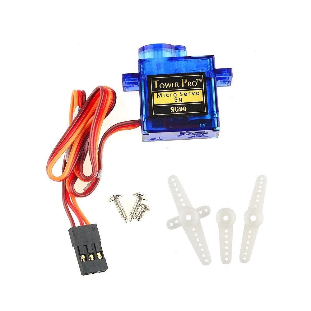
This figure is nothing I know, but it's a start at least. After doing some research about the servos I purchased, it looks like these servos, that are branded TowerPro may be counterfeit. However I know that my USB port can barely handle Arduino with some sensor and a servo moving around so I guess it could easily be 100 mA. The datasheet of the servo does not mention any current draw (max, min, average, etc.


I could easily use a 5V battery but why bother? :) Aside from this not funny joke, I'd like to put to good use my little knowledge of electronics gained at University.
#TOWER PRO MICROSERVO CODE#
Once you have the maximum and minimum duty cycle's you can use the following code to create the scan effect shown in the introductory video. You will need to be running idle3 as sudo since we are controlling the GPIO pins. For my pan servo, the minimum duty cycle was 3% and the maximum was 11%, with the centre at 7%. Note the values just before the limits, you might have to use 0.5% increments towards the end. Start with the theoretical duty cycle values above and then gradually move them up and down. # Create PWM channel on the servo pin with a frequency of 50Hzĭuty_cycle = float( input( "Enter Duty Cycle (Left = 5 to Right = 10):")) # servo_test.py - Test functionality of SG90 Micro Servo # Written By: David Such import RPi.GPIO as GPIOĭuty_cycle = 7.5 # Should be the centre for a SG90 # Configure the Pi to use pin names (i.e. Load up the following servo_test.py program on your Pi and then run it. I'm using a 2A supply so one servo is fine (even stalled). You may draw current from the +5 V pins provided the sum of that current and the board's 700 mA doesn't exceed the supply you provide to the board. Use the current draws from the data sheet above. The Pi draws approximately 700 mA from the +5 V supply. You can power (V cc) the servo from the Raspberry Pi 5V pin but do your current calculations first.

Although the servo runs off a nominal 5V, there is no problem controlling it with the 3.3V levels of the Pi since that is still above the logic high threshold.
#TOWER PRO MICROSERVO DRIVER#
You can use any GPIO pins you want, I used GPIO 5 because it doesn't conflict with the motor driver board and speaker pHat which will also be mounted on Alexa M.


 0 kommentar(er)
